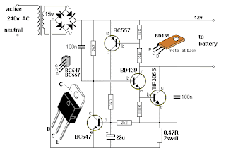
The 12v Trickle Charger circuit uses a TIP3055 power transistor to limit the current to the battery by turning off when the battery voltage reaches approx 14v or if the current rises above 2 amp. The signal to turn off this transistor comes from two other transistors - the BC557 and BC 547.
Firstly, the circuit turns on fully via the BD139 and TIP3055. The BC557 and BC 547 do not come into operation at the moment. The current through the 0.47R creates a voltage across it to charge the 22u and this puts a voltage between the base and emitter of the BC547. The transistors turn on slightly and remove some of the turn-on voltage to the BD139 and this turns off the TIP3055 slightly.
This is how the 2 amp max is created.
As the battery voltage rises, the voltage divider made up of the 1k8 and 39k creates a 0.65v between base and emitter of the BC557 and it starts to turn on at approx 14v. This turns on the BC 547 and it robs the BD136 of "turn-on" voltage and the TIP3055 is nearly fully turned off.
All battery chargers in Australia must be earthed. The negative of the output is taken to the earth pin.
source : http://www.talkingelectronics.com.au/projects/200TrCcts/200TrCcts.html


0 comments